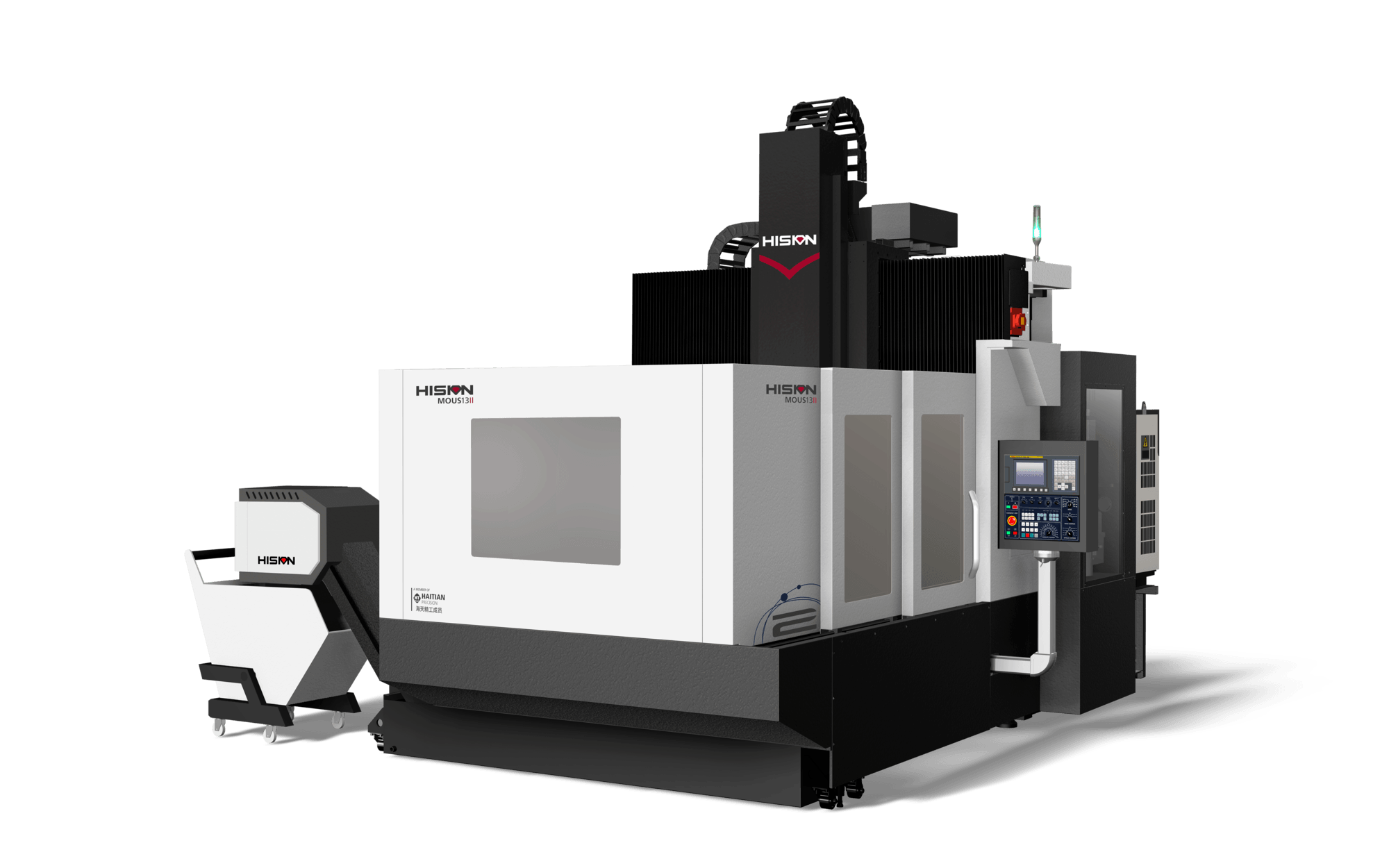
[Application Case] Air compressor shell processing
2021-08-19
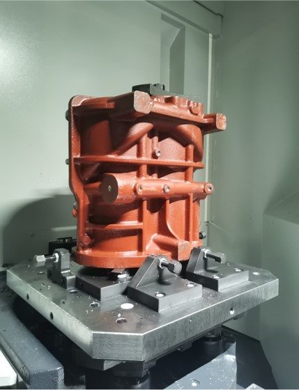
Air compressor shell structure
The air compressor shell is provided with a plurality of installation parts with installation holes of different sizes which are connected with the shell through a plurality of support ribs, the shell is provided with the same number of lubrication holes as the installation parts, and the installation holes of each installation part are connected with at least one lubrication hole. A plurality of lubrication channels vertically and horizontally distributed are arranged in the support rib, and each lubrication hole is connected with at least one lubrication channel, so as to improve the space for storing lubricating oil in the shell. When no lubricating oil is injected, the lubrication channel and lubrication hole play a role in radiating heat inside the shell. The bottom of the shell is respectively provided with four supporting legs provided with fixing holes.
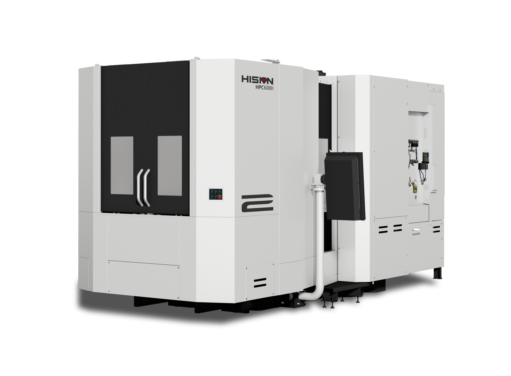
Machine tool: HPC600Ⅱ Horizontal Machining Center
Main features
The large basic parts of the new generation of HPC600Ⅱ horizontal machining center have been analyzed and calculated, and the rib cavity structure has been optimized. The thick one-piece bed, combined with three-axis heavy-duty ball guides and equipped with an integrated high-speed electric spindle, can cope with the processing of various materials from high speed, high precision to heavy cutting and from aluminum and steel to castings, so the bed is widely used in precision machining for automobiles, aerospace and plastic machinery.
Main parameters
- Three-axis travel X/Y/Z: 800/800/850mm
- Bed dimension: 500mm×550mm
- Workbench bearing capacity: 1,000kg
- Fast moving speed X/Y/Z: 60/60/60m/min
- Spindle speed: 8,000rpm
- Spindle power: 26/45kW
- 7. Spindle torque: 305/623N?m
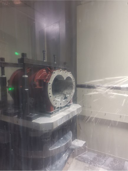
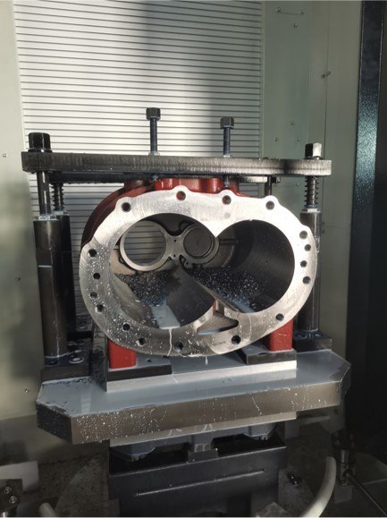
Processing flow: horizontal plus flexible automatic production line
Haitian Precision Horizontal plus Flexible Automatic Production Line suitable for processing various box bodies, valve blocks, shells, brackets and other parts can clamp a variety of different parts at one time and work continuously for 24 hours. In addition to greatly improving manufacturing flexibility and production efficiency, the flexible automatic production line realizes a flexible mass production mode, shortens the production cycle, guarantees product quality, and reduces production costs to obtain better benefits.
Product processing technology
OP10: the workpiece contacts the tooling with the bottom surface of the blank. As each blank is quite different, a square shall be used for correction and clamping during installation. The first sequence is mainly drilling and thread and the use of composite drill can improve the processing efficiency. Some holes are 100-200mm deep, so the machine tool must be equipped with central water outlet.
OP20: there are three points to pay attention to in the second sequence.
I: a boring cutter with a diameter D180 and a length of H350 shall be used for the splayed hole, and the speed shall not exceed S250 to prevent vibration.
II: milling, drilling and tapping are required at the bottom of the splayed hole, and the length and speed of the tool rod shall reach 400mm. Therefore, it is more appropriate to select the shockproof tool rod for the milling disc. For the tool handle for drilling and tapping, attention shall be paid to the interference between the tool handle and the workpiece.
III: as the depth of D8 and D9 is 320mm, it is necessary to drill the pilot hole first, then cooperate with the gun drill to process, and ensure the pressure of the center water outlet.

